This service may collect data about your activities. Please inform yourself about the service and agree to the use of YouTube Video.
FAQ TQ-RoboDrive
In the following we have briefly and concisely summarized the answers to many frequently asked questions (FAQs). You will find them broken down according to topics and products.
If your question is not listed, please feel free to contact us directly at any time.
ILM/ILM-E Servo-Kits FAQ
What is the difference between ILM “STD” and ILM “HS” version?
The standard (STD) and high speed (HS) versions of our stators are different in the iron alloy and the thickness of the laminates. In the “HS version” we use an alloy, which reduces the dynamic losses at higher rotational speeds. This is possible by re-magnetization of the iron (hysteresis losses and eddy current losses). The datasheet is the same for both versions.
What are the primary differences between ILM and ILM-E frameless servo-kits?
The ILM Stator is cast with epoxy resin while the ILM-E have open windings with are glued. Furthermore, the ILM-E has plastic pole caps instead of insulating paper like it is by the ILM Stator. The ILM Stator has THT hall and temp sensors and the ILM-E has SMD hall and temp sensors.
How are the ILM and ILM-E Servo-kits integrated?
The ILM Stator is integrated into the housing by gluing while the ILM-E Stator is shrink fitted into the housing.
But the integration of the rotor is for ILM and ILM-E the same. They both will glued on to the shafts.
Take a look at the instructions from the TQ-ILM-E integration:
What category of motors does your frameless servo-kits belong to?
Our ILM and ILM-E Servo-kits belongs to permanent magnet synchronous motors (PMSM) category with sinusoidal Back-EMF waveform.
How is the rated voltage defined for your frameless servo-kits?
The rated voltage is a design criterion and was defined to 48 V (or 24 V for ILM25/38). Our motors meets all the requirements f. e. “UL standards, EC guidelines and ISO DIN EN standards”.
How are the current values defined for your frameless servo-kits?
Our servo-kits have four times of overload capacity with 20 % of linear saturation. The Peak current is measured as the current at which the motor torque constantly drops by 20% of its nominal value. If you dividing this peak current value by 4 you will receive the rated current of the motor.
How are Motor torque constant and Back-EMF constant related to each other?
The motor torque constant kT{ Nm/A } and the Back-EMF constant kE{ V/krpm } hold the following relationship for our servo-kits:
(√3/2) * (60/2π) * kE
How does Induced voltage vary with No-load speed?
The Induced voltage varies linearly with No-load speed of the motor.
How can I calculate the motor electrical time constant?
The motor electrical time constant can be calculated by using the terminal resistance and terminal inductance values from the datasheet as:
te = LTT/RTT
How can I measure the motor rated speed from the T-N plot in the datasheets?
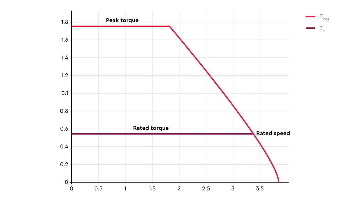
Our motors were measured only for maximum No-load speeds. However, once can find out the Rated speed of our motor using the T-N plot for a specific interconnection in the datasheet as shown in the picture:

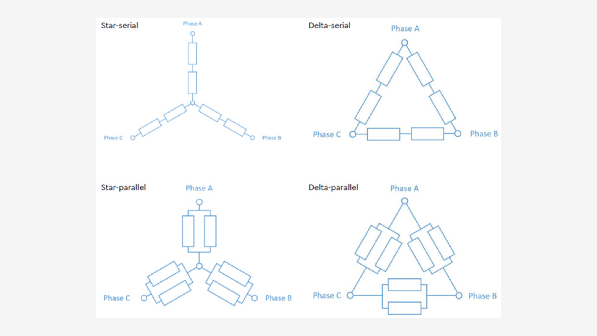
What is the available stator-winding configuration of “TQ Frameless Servo-kits”?
The variation in the stator-winding configuration comes from our interconnection PCB that is soldered to the 12 pins of the stator. We can offer the following interconnections for our Servo-kits:

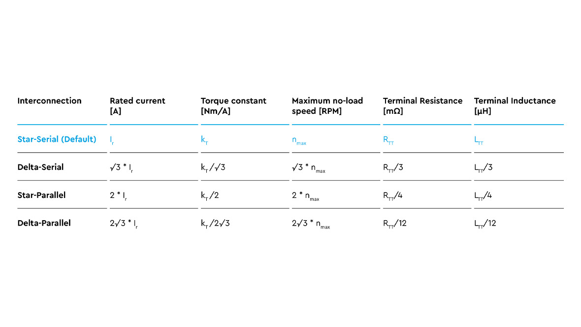
How does the change in winding interconnection influence the motor parameters?
For a given supply voltage, the rated and peak torques, copper losses and efficiency remains constant throughout all the interconnections.
The other parameters that change for all the available interconnection is presented in the table below:

Why is the motor torque constant not linear at peak torque?
According to our test bench measurements, the motor torque constant is not linear throughout the torque range but tends to go into a linear saturation of 20% at peak torque.
Is the Rated current a peak value or an RMS value?
The rated current value is specified in our datasheet as peak value.
How does the motor performance vary with ambient temperature?
All our datasheet parameters were measured at a room temperature of 20-22°C. According to our S1 curves the ability of the motor to produce a continuous torque drops with increasing the ambient temperature. This point has to be considered while choosing a suitable motor size for the customer application.
How did your frameless servo-kits achieve high torque density?
The main reasons for our industry leading torque density are:
- Very high copper fill factor through ortho-cyclic single-tooth winding
- Precise geometry of sheet metal cutting and the ratio of copper to Iron
- Good thermal connection of the stator to the housing by using a thermally conductive glue along with the vacuum potting of the stator windings
How are the copper losses calculated for “TQ Frameless Servo-kits”?
The copper losses are calculated during a steady-state operation by the formula:
PΩ = 3 * (Irated/√2)2 * RTT/2
What is the maximum operating temperature of your Frameless Servo-kits?
The maximum operating temperature of our frameless servo-kits is 125 °C.
Do you offer “Hall sensors” and “Temperature sensors” with your servo-kits?
Yes we offer Hall and temperature sensors. The ILM-E has hall and temperature sensor inclusive. The ILM has temperature sensors inclusive and hall sensors is with a surcharge possible.
Why do I need a double rotor or an elongated rotor for the Hall version of an ILM servo-kit?
The reason is that the Hall sensors are on top of the PCB. The normal Stator is to short and so you need an extension. Otherwise, the Hall sensor can´t detect the rotor position accurately.
What are the requirements from the servo-Drive/Inverter side?
Our servo-kits require a Servo-Drive/Inverter that can support a sinusoidal commutation and have a PWM frequency higher than 16 kHz.
Would you recommend any suitable Servo-Drive/Inverter?
We recommend the Servo-Drives/Inverters from Elmo Motion Control and Synapticon. The products from both companies work well with our motors.